- 您现在的位置:买卖IC网 > Sheet目录1905 > ATMEGA8HVA-4CKU (Atmel)MCU AVR 8K FLASH 4MHZ 36-LGA
170
8024A–AVR–04/08
ATmega8HVA/16HVA
29.5
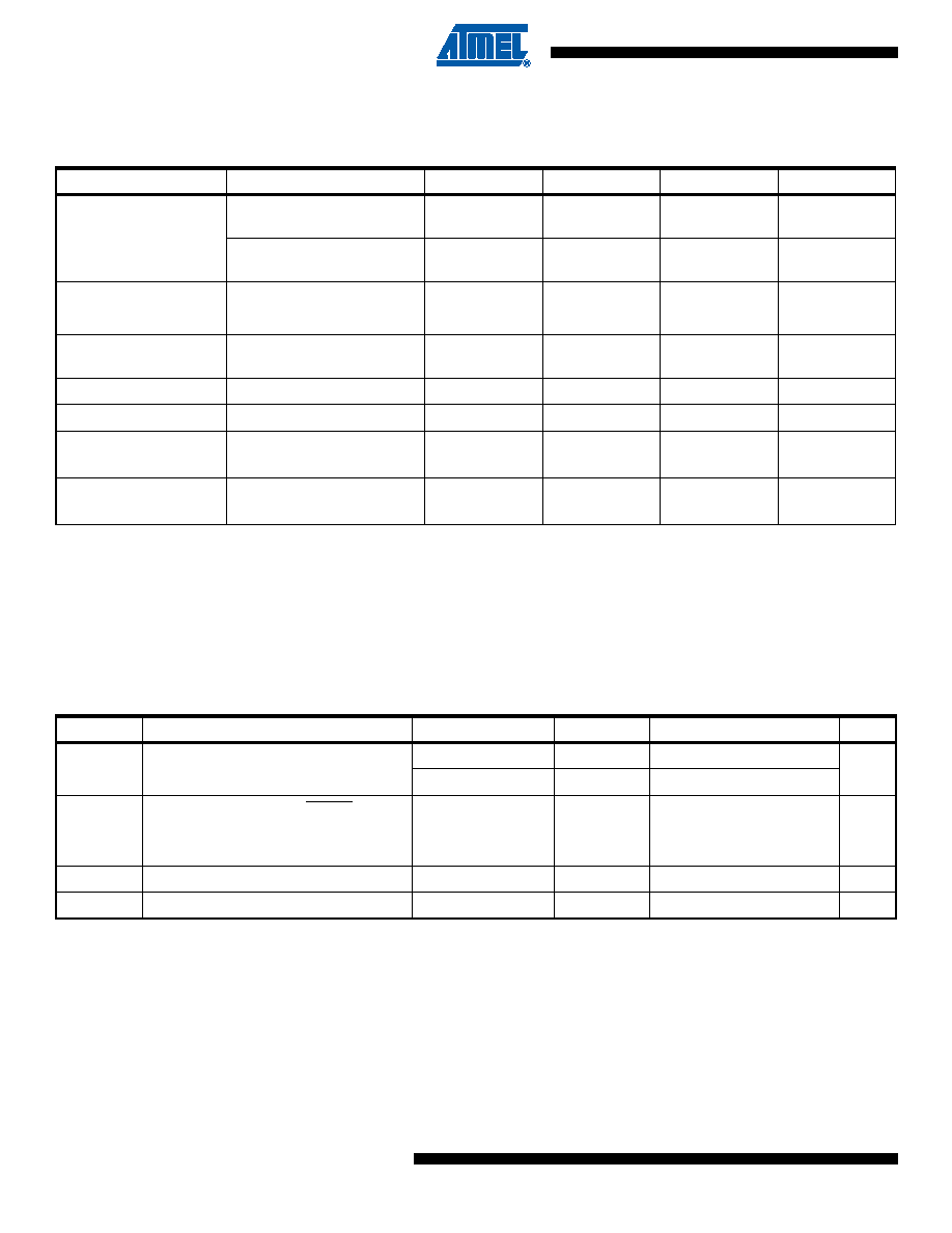
FET Driver Characteristics
Notes:
1. All DC Characteristics contained in this data sheet are based on simulation and characterization of other AVR microcontrol-
lers manufactured in the same process technology. These values are preliminary values representing design targets, and
will be updated after characterization of actual silicon.
2. These numbers assume the use of one external N-channel FET of model TPCS8210. If other FETs are used, the numbers
may deviate somewhat. The equivalent capacitive loads at OC and OD are around 1.2 nF. Rise and fall times scale approxi-
mately proportional to the capacitive loading
3. Not tested in production.
29.6
Power-on and Reset Characteristics
Note:
1. The voltage at the Pack + terminal will be slightly higher than V
POT when the chip is enabled. This is because of an internal
Pull-down current on the BATT pin in the range 50 - 110 uA and the RBATT resistor connected between the Pack + terminal
and the BATT pin. R
BATT = 1k gives a voltage drop 0.05 - 0.11V.
Table 29-5.
FET Driver Outputs specification
A = -10°C to 70°C unless otherwise specified)
Parameter
Condition
Min.
Typ.
Max.
Units
VFET DC level(2)
1 cell DUVR operation,
VREF = 1.100V
1.9
2.0
2.1
V
2 cell DUVR operation,
VREF = 1.100V
3.8
4.0
4.2
V
VFET ripple(2)
1 cell DUVR operation
±0.1
V
2 cell DUVR operation
±0.1
V
OC, OD clamping
voltage
14.0
V
OC, OD
Normal ON operation
VFET + 2.5
VFET + 4
VFET + 6.5
V
OC, OD
Normal OFF operation
0.0
0.1
V
(OC, OD, 0 - 90 %)
Normal ON operation
1
2
ms
Falltime(2)(3)
(OC, OD, 100 - 10 %)
Normal OFF operation
5
10
s
Table 29-6.
Reset Characteristics(T
A = -10°C to 70°C unless otherwise specified)
Symbol
Parameter
Condition
Min
Typ
Max
Units
VPOT
Power-on Threshold Voltage(1)
VFET = 8.4V
2.75
3.65
4.1
V
VFET = 4.2V
2.75
3.5
3.95
tRST
Minimum pulse width on RESET Pin
900
ns
VBOT
Brown-Out Detection (BOD) Trigger
Level
2.9
V
VHYST
BOD Level Hysteresis
100
mV
V
BLOT
Power-off Threshold Voltage
2.4
V
发布紧急采购,3分钟左右您将得到回复。
相关PDF资料
ATSAM3N4AA-AU
MCU FLASH 48-QFP
ATSAM3SD8CA-CU
IC MCU 2X256KB CORTEX-M3 100-QFN
ATSAM3U1EB-CU
IC MCU 64KB CORTEX-M3 144-TFBGA
ATSAM3X8EA-CU
IC MCU 2X256KB CORTEX-M3 144-BGA
ATTINY12V-1SUR
IC AVR MCU 1K FLASH 4MHZ 8-SOIC
ATTINY13-20SQR
IC MCU AVR 1KB FLASH 20MHZ 8SOIC
ATTINY13A-MMUR
MCU AVR 1KB FLASH 20MHZ 10DFN
ATTINY13V-10SUR
MCU AVR 1KB FLASH 10MHZ 8SOIC
相关代理商/技术参数
ATMEGA8HVA-4CKUR
功能描述:8位微控制器 -MCU AVR 8KB FLSH 512B EE 1KB SRAM - 4 MHZ RoHS:否 制造商:Silicon Labs 核心:8051 处理器系列:C8051F39x 数据总线宽度:8 bit 最大时钟频率:50 MHz 程序存储器大小:16 KB 数据 RAM 大小:1 KB 片上 ADC:Yes 工作电源电压:1.8 V to 3.6 V 工作温度范围:- 40 C to + 105 C 封装 / 箱体:QFN-20 安装风格:SMD/SMT
ATMEGA8HVA-4TU
功能描述:8位微控制器 -MCU AVR 8KB, 512B EE 4MHz 1KB SRAM 1.8-9V RoHS:否 制造商:Silicon Labs 核心:8051 处理器系列:C8051F39x 数据总线宽度:8 bit 最大时钟频率:50 MHz 程序存储器大小:16 KB 数据 RAM 大小:1 KB 片上 ADC:Yes 工作电源电压:1.8 V to 3.6 V 工作温度范围:- 40 C to + 105 C 封装 / 箱体:QFN-20 安装风格:SMD/SMT
ATMEGA8HVA-4TUR
功能描述:8位微控制器 -MCU AVR 8KB FLSH 512B EE 1KB SRAM - 4 MHZ RoHS:否 制造商:Silicon Labs 核心:8051 处理器系列:C8051F39x 数据总线宽度:8 bit 最大时钟频率:50 MHz 程序存储器大小:16 KB 数据 RAM 大小:1 KB 片上 ADC:Yes 工作电源电压:1.8 V to 3.6 V 工作温度范围:- 40 C to + 105 C 封装 / 箱体:QFN-20 安装风格:SMD/SMT
ATMEGA8HVD-4MX
功能描述:8位微控制器 -MCU AVR 8KB, 512B EE 4MHz 1KB SRAM 2.1-8V
RoHS:否 制造商:Silicon Labs 核心:8051 处理器系列:C8051F39x 数据总线宽度:8 bit 最大时钟频率:50 MHz 程序存储器大小:16 KB 数据 RAM 大小:1 KB 片上 ADC:Yes 工作电源电压:1.8 V to 3.6 V 工作温度范围:- 40 C to + 105 C 封装 / 箱体:QFN-20 安装风格:SMD/SMT
ATMEGA8L-8AC
功能描述:8位微控制器 -MCU AVR 8K FLASH 512B EE 1K SRAM ADC 3V RoHS:否 制造商:Silicon Labs 核心:8051 处理器系列:C8051F39x 数据总线宽度:8 bit 最大时钟频率:50 MHz 程序存储器大小:16 KB 数据 RAM 大小:1 KB 片上 ADC:Yes 工作电源电压:1.8 V to 3.6 V 工作温度范围:- 40 C to + 105 C 封装 / 箱体:QFN-20 安装风格:SMD/SMT
ATMEGA8L8AI
制造商:Atmel Corporation 功能描述:
ATMEGA8L-8AI
功能描述:8位微控制器 -MCU AVR 8K FLASH 512B EE 1K SRAM ADC 3V RoHS:否 制造商:Silicon Labs 核心:8051 处理器系列:C8051F39x 数据总线宽度:8 bit 最大时钟频率:50 MHz 程序存储器大小:16 KB 数据 RAM 大小:1 KB 片上 ADC:Yes 工作电源电压:1.8 V to 3.6 V 工作温度范围:- 40 C to + 105 C 封装 / 箱体:QFN-20 安装风格:SMD/SMT
ATMEGA8L-8AJ
功能描述:IC MCU AVR 8K 5V 8MHZ 32-TQFP RoHS:是 类别:集成电路 (IC) >> 嵌入式 - 微控制器, 系列:AVR® ATmega 标准包装:9 系列:87C 核心处理器:8051 芯体尺寸:8-位 速度:40/20MHz 连通性:UART/USART 外围设备:POR,WDT 输入/输出数:32 程序存储器容量:32KB(32K x 8) 程序存储器类型:OTP EEPROM 大小:- RAM 容量:256 x 8 电压 - 电源 (Vcc/Vdd):4.5 V ~ 5.5 V 数据转换器:- 振荡器型:内部 工作温度:0°C ~ 70°C 封装/外壳:40-DIP(0.600",15.24mm) 包装:管件